 Water usage tracking
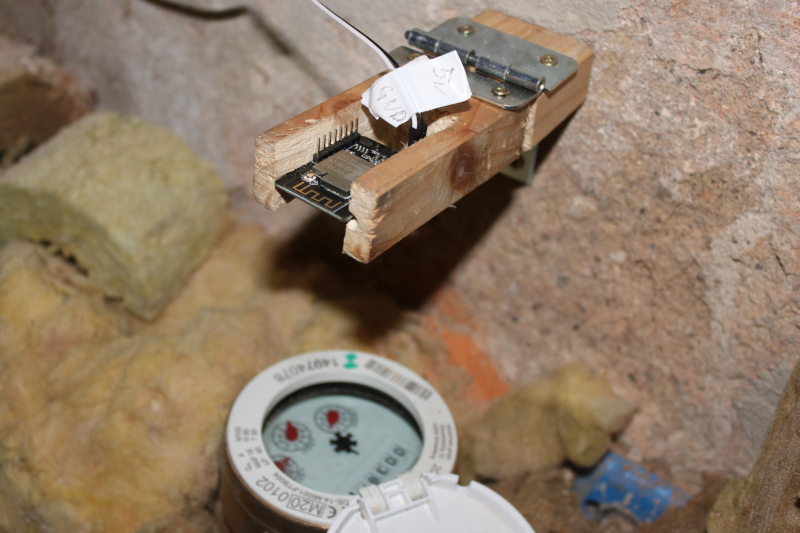
We log our water usage over time in Grafana. To do so, we have two small devices next to our main water meter and warm water meter respectively. They periodically read the meter by taking a picture and recognizing digits in it (currently every 5 minutes). This page describes how those devices are set up, how to maintain them and how to install similar ones elsewhere.
Overview
The device is an ESP32-CAM board with an OV2640 camera module. It can be obtained from many suppliers (we use this one). The software on the device is the AI-on-the-edge-device firmware, which does the digitization and upload to InfluxDB directly from the board itself. General documentation for this firmware is available on its GitHub wiki, this document focuses on the Kanthaus-specific parts.
Setting up the device
First, we need a power source (5V DC) for the board. We have plenty of such adapters in the electronics workshop, all that is needed is to solder the appropriate connectors to plug the power source to the board.
The camera that comes with the device is set up for a focal length that is not adapted to this use, so we need to rotate the objective to obtain a sharp image of the meter at a close distance. This requires removing the glue which holds the objective in
place. This step is quite fiddly, do not bring the lens too close to the sensor either or you could break the camera.
The device comes with a default firmware which lets you stream from the camera over WiFi, which helps with checking the sharpness as you make changes. To do so, connect the device to a power source and connect to the WiFi network it creates. Then, go to http://192.168.4.1/ and you are able to stream directly from the device's camera.
The devices use by default an internal WiFi antenna which is not very strong. It is very advisable to use the external antenna instead, but that requires unsoldering a very small resistor and soldering it in another position, which requires some skill.
Network settings
The devices are connected to the kh-iot WiFi network, which means it has limited network access.
Their IP addresses are static:
192.168.5.37for the main water meter192.168.5.38for the warm water meter
To access its web UI connect to the kh-admin network and go to http://192.168.5.37/ (or http://192.168.5.38/ for the warm water meter). If you are outside of Kanthaus, use SSH port forwarding via kanthaus-server, such as ssh -L 8080:192.168.5.37:80
kanthaus-server, and then point your browser to http://localhost:8080/.
The network settings for the device can be changed by taking out the SD card in it and modifying the wlan.ini file on the card.
Updating the firmware
The firmware can be updated in two ways:
- either via the web interface
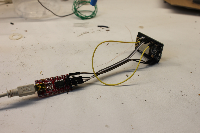
- or by flashing the device directly, using a USB-to-Serial adapter. We have one in the electronics workshop for this.
To flash via USB, the connections look like this:
Flashing the device requires three binary files, which can be copied to device using esptool.py (which can be installed with pip install esptool):
esptool.py erase_flash
esptool.py write_flash 0x01000 bootloader.bin 0x08000 partitions.bin 0x10000 firmware.bin
Training the digitizer
Before the device can read the meter, it needs to be calibrated. This would need to be done again for instance when our water meter is renewed. This can be done from the web UI directly. Refer to the official documentation for more details about the process.
Development environment
The official documentation recommends to use VSCode with the PlatformIO extension to develop, but sadly PlatformIO is not available for VSCodium at the time of writing this.
Instead you can relatively easily work with a text editor, and install PlatformIO in a Python virtualenv (from the code/ subdirectory of the repository):
python3 -m venv .venv
source .venv/bin/activate
pip install platformio esptool
and then you can compile the firmware with
platformio run --environment esp32cam
This generates the three .bin files required for flashing in the .pio/build/esp32cam subdirectory.
For debugging purposes it is useful to use the USB-to-Serial adapter to see detailed logs. First, connect the adapter to the device (by crossing the RX/TX wires and connecting GND and +5V). Then, locate the USB-to-Serial adapter by listing the USB devices before and after plugging in. Once you have the path to the device, you can then open it with: screen /dev/ttyUSB0 115200. If screen terminates immediately you might need to add your user to the dialout group, see the detailed instructions for serial communication with ESP32.